Early ATM at University of Cambridge and Olivetti Research
David Greaves
Cambridge Fast RingThe Cambridge Fast Ring was a development of the Cambridge Ring and came before the Cambridge Backbone Ring  The Cambridge Fast Ring (CFR) was designed by Andy Hopper, Roger Needham, Steven Temple, John Porter and others. It was a 100 Mbit/second LAN using 32-byte cells. The project was sponsored by Acorn Computer. The header of the cell was 4 bytes. Unlike the subsequent ATM standard, there was no cell header error check, but there was a 16-bit CRC at the end of each cell that covered header and payload. The CFR built on the success of the Cambridge Ring. It was designed to run 10 times faster and had a slot size of 38 bytes instead of 38 bits. It was integrated into a two-chip set with the ECAD tools being designed locally. I (DJG) was the person who designed and built the first circuit-boards for the chipset and got the system working. The integrated circuits were designed using the local 'Cambridge HDL' hardware description language that originally ran on the Cambridge Distributed System and then was ported to Modula-2 and ran on Microvax Ultrix (donated by Digital Equipment Corp). Repeater Card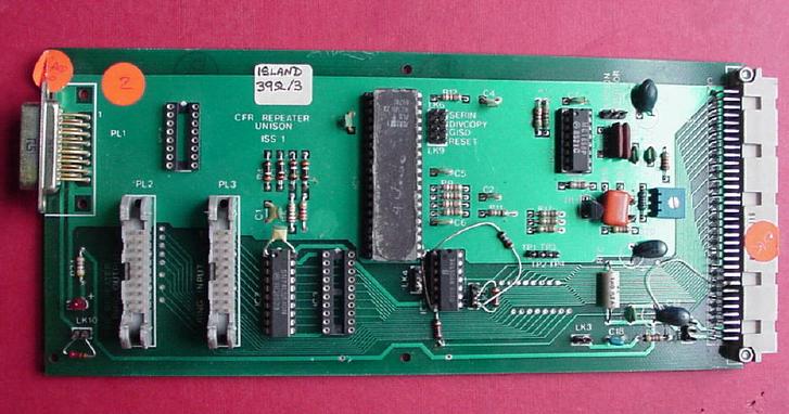 The repeater card contains the ECL chip, whose job it was to convert from 100 Mbps serial to 12.5 MHz byte parallel. CMOS could not run at these speeds in 1985. The repeater card contains this ECL chip and also a VCO for timing recovery. Transformers (missing from their 16 pin socket in this photo) coupled the line to the cable. The cable used a pair of twisted pairs for receiving from the previous station and another pair for sending to the next station. As per the 10 Mbps Ring, a change on one pair denoted a zero and a change on both denoted a one. At the higher data rate of 100 Mbps, the skew between the two cables was a significant souce of jitter, since the timing information from a zero depended on which cable it was received on. The repeater connected to the station card in two ways. Either via a pair of 20 pin ribbon cables, one for send and one for receive, or over the back panel DIN connector. Station Card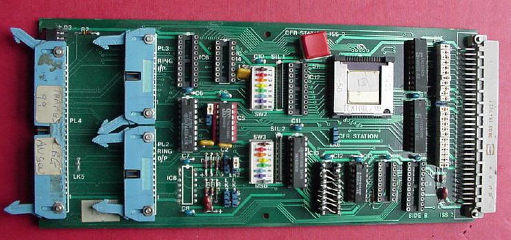 The station card contains the CMOS chip and the 64 kbit DRAM. The station card could be wired one-to-one with a repeater card or a small cluster of stations could be chained off one receiver in a parallel form of the ring. Alternatively, a set of station cards could be wired in parallel to form a ring-in-a-box. An extender station containing an SRAM was also needed to pad such a small ring out so that it contained at least one slot. The station chip in this illustration was one of the very first samples. Its lid is fixed on with sellotape and could be taken off when we had to probe the chip for debugging. The 16 DIL switches were used originally to set the station address. However, we soon moved over to an ATM style of operation where a station did not have a specific address. Instead, ones were entered by the host in the DRAM for virtual circuits that the station desired to receive. Manchester Repeater Card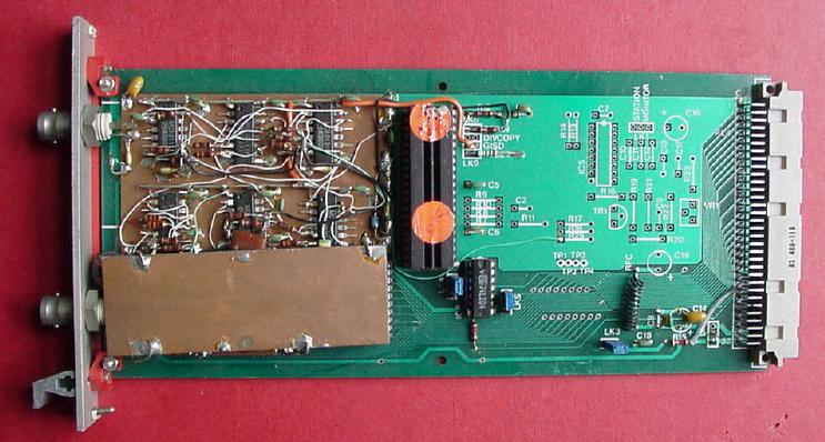 As an experiment, I constructed three identical Manchester Repeater Cards. These used a pair of 50 ohm BNC cables, one for send and one for receive. The manchester coding was implemented with six 10K MECL integrated circuits. The copper plate at the bottom left provides some screening for the LC tank circuit used for clock recovery. VME CFR Network Interface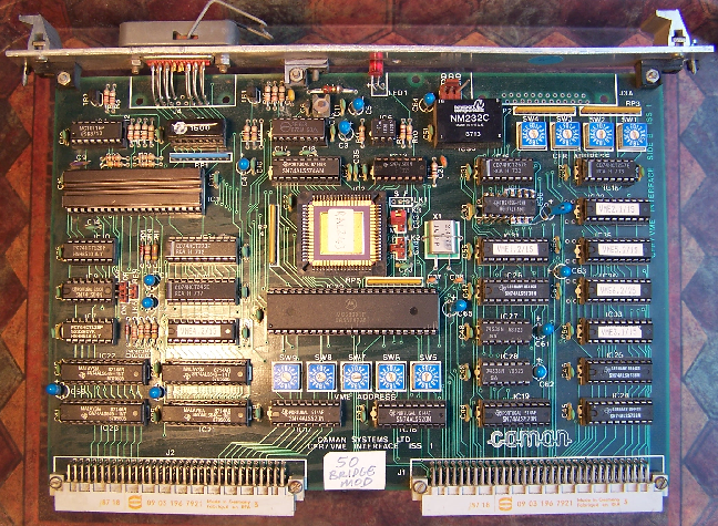 A local company, Caman Systems, developed a number of fast-ring based products. Pictured is a VME bus network interface card (NIC), that included the repeater and station functions on a single PCB. PALs are used as glue logic to implement the bus interface. A set of six rotary DIL switches sets the base address of the card in VME address space. The four rotary switches to set the station address were seldom used, since we quickly moved over to ATM-style protocols with every station running in 'bridge mode' where the DRAM was used for VCI lookup to filter the active virtual circuits to be received. Further info: A Hopper and RM Needham. The Cambridge Fast Ring Networking System. IEEE Transactions on Computers, 37(10), October 1988. `Yes', 48 Byte ATM Card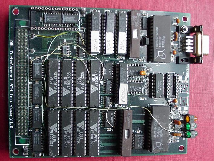 This was the first card constructed in Cambridge that used 48 byte ATM cells. It was a major wrench for us to switch to 48 bytes since, at that time, the number of 32 byte hosts and switches at the two sites probably exceeded 100, making it one of the largest ATM projects in the world. The pictured card, known as the Yes Board, used the AMD Taxi chips for 100 Mbps transmission on twisted pair. The mapping of ATM cells to TAXI frames was designed by Xerox Parc and became one of the first ever ATM Forum recommendations. This card was designed for the DEC Turbochannel but I also built a Turbochannel to VME adaptor so that a number of cards could be installed in one VME rack. The card was very, very simple, with cell payloads being sent and received directly into FIFOs. The host performed segmentation, reassembly and source rate contol. An optimisation in a later version was not to interrupt the host unless a cell with its header flag set was received, thereby indicating end of datagram. The idea of a header flag was adopted in AAL-5. ATM25 NICVarious variations on the above NIC were implemented: moving to an ISA Bus, adding an onboard ARM processor and changing from 100 Mbps TAXI to 25 Mbps. 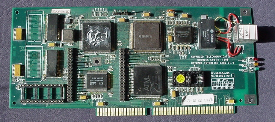 This card shows one of the earliest ATM-25 NICs made by ATM Limited (now GlobespanVirata). The PHY device from the IBM 16 Mbps token ring is used with 4B5B coding instead of Manchester coding, resulting in 25.6 Mbps. The ATM Forum decided to re-pin the RJ45 connector after we had made hundreds of prototypes, hence the four red wires on this card instead of the balun (one is yellow actually). The line interface chip had to have a respin, and this particular card has a ceramic-packaged early prototype on that site. The two rows of pins could accept various expansion cards, including a POTS card that enabled the desktop phone to be terminated: thus illustrating the multi-media capabilities of ATM. ATM LimitedIn 1993 we started a company called Advanced Telecommunications Modules Limited. The plan was to develop wired ATM networking for the home. We sold to Ralph Ungermann a license to our technology: he wanted to develop ATM to the desktop in the office environment. This became an early focus for ATM Ltd as well. The three initial products we developed were: 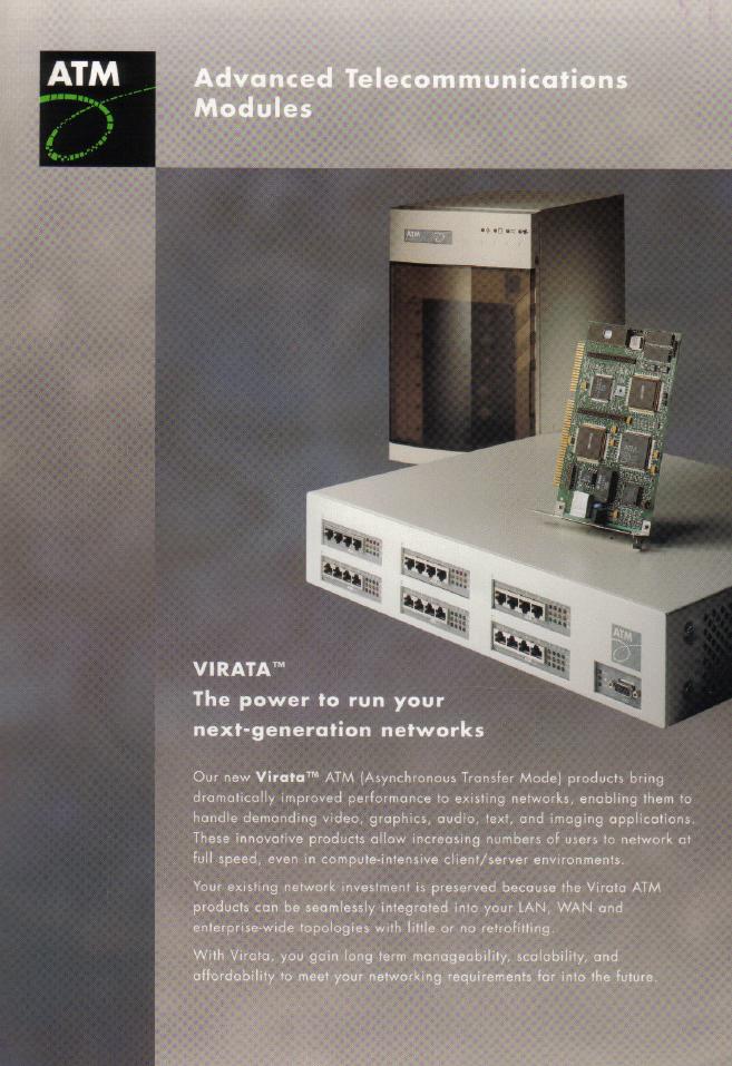 |
Copyright 1985-2002 DJ Greaves. Cambridge Backbone Ring ADSL Home Shopping DJG HOME.