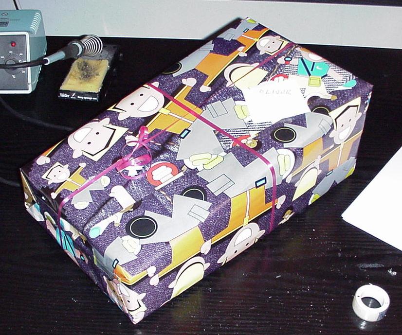
| Here is a box, a mysterious box. Set up and ready to go. But this box can hide a secret. Can you guess what's inside it today ? Click HERE to open the box and find out what's inside. |
Olbuzz Buzzer Board - Chapters
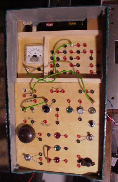
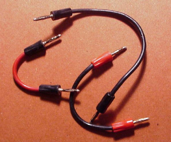
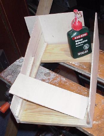
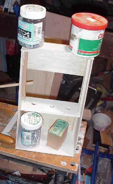
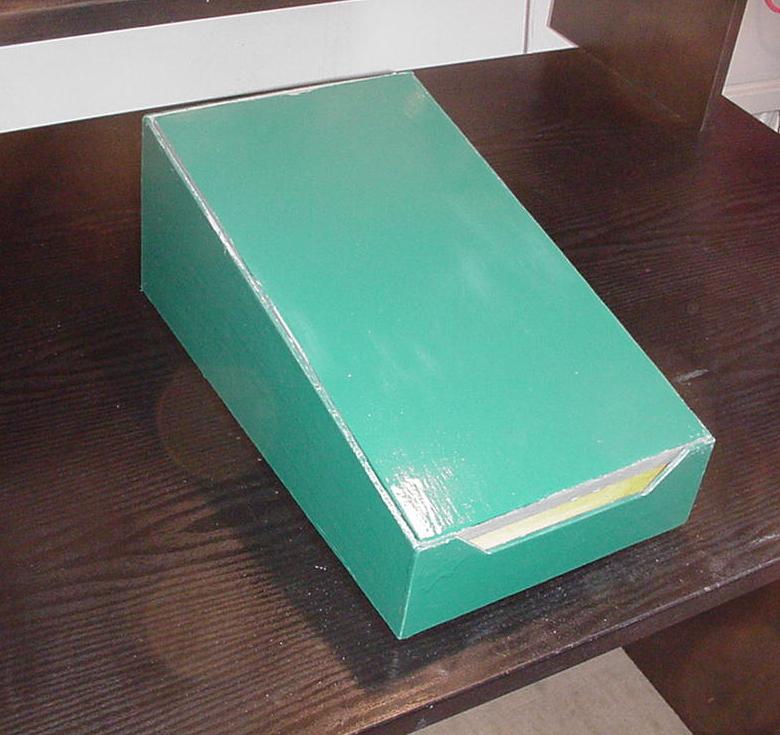
This article describes a small control panel designed for someone who is fixated with knobs, lights and buzzers. I call it the Buzzer Board after the ones my uncle used to make when I was child. The main components are switches and lights, but also a pair of buzzers, a diode, and a relay and capacitor are provided. Electric power is supplied via a 100 second timer so that the unit cannot be left on accidentally. The components are wired together by putting little patch cables into sockets. The sockets are set up so that no possible wiring can short out the battery or lead to a harmful circuit. This page is under construction. A user manual will be provided soon. Black push switch . Panel meter. Box ConstructionThe box was made of thin plywood with wooden dowl batterns to line each joint. It was assembled over a number days using just wood glue, with no pins or nails. Weights were used to push each joint together while it set.
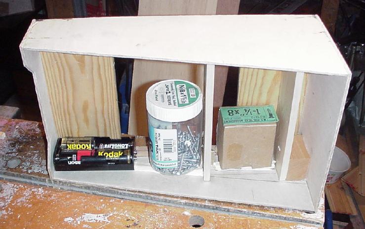
To provide extra strength, fat cross-batterns were added wherever possible. This helps it to resist general abuse by young persons, including, perhaps, use as a stepladder.
The frosting visable in the following photo is actually the perspex panel that guards the top panel section. It is half in position in this photo.
Front Panel
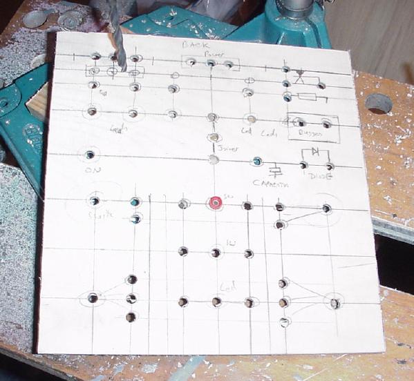
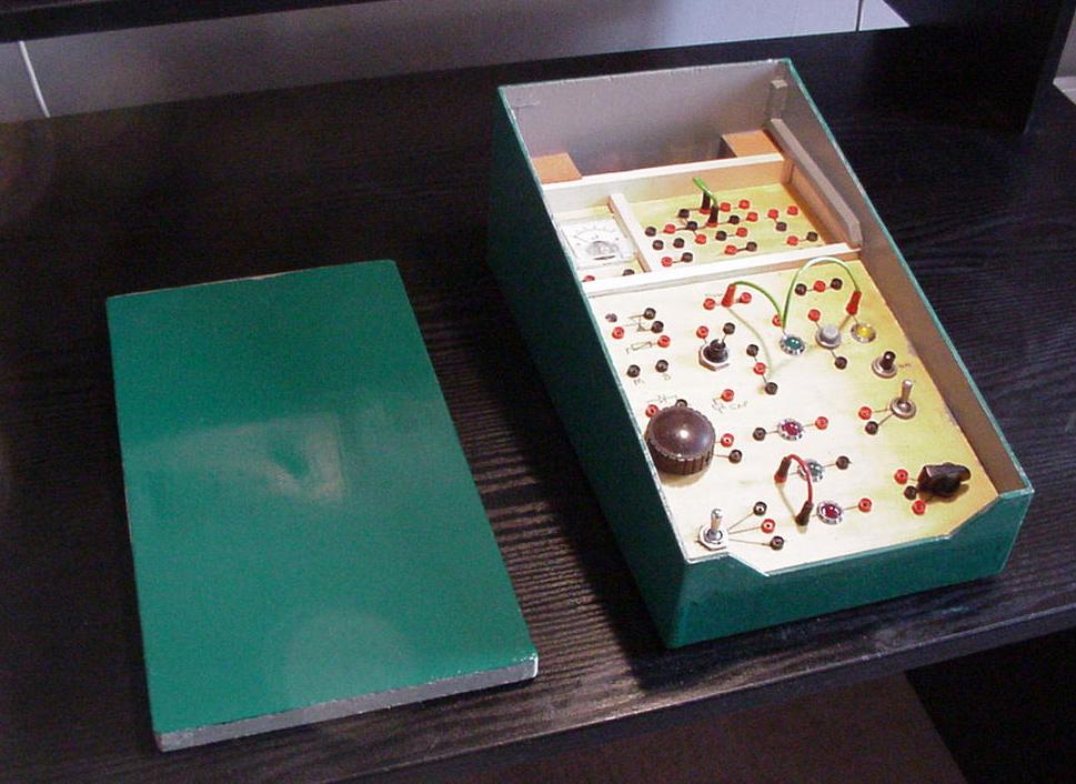
The front panel was marked out on the rear side to take a number of switches, lights and other components. Then it was drilled where marked. A light coat of varnish was applied to the front side and then the components were all installed. For each connection to each component, a 2 mm jack socket was supplied. Finally, when all the wiring was in place, two strengthening members were added and then, not shown, all of the components were covered with a thick layer of hot-melt glue. This layer keeps the components firmly in place against future robust handling.
Top Patch Panel
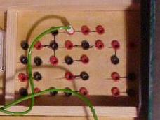
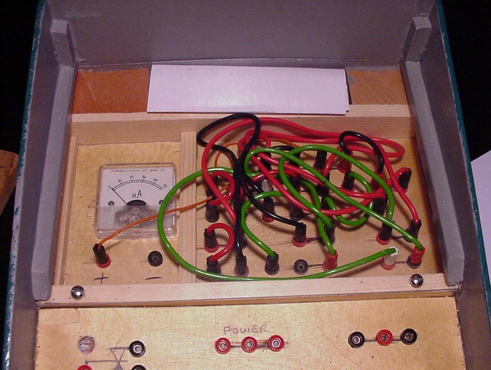
A dedicated section at the top of the unit contains a patch panel and the battery compartment. The patch wires are too small to be handled by a very young person. Instead they would get eaten. Therefore the top panel provides a way of setting up a circuit and locking it away. It is covered with a perspex panel that is screwed in place. This patch panel mirrors most of the connections on the main panel and so a circuit can be set up on the top panel instead of the main panel. For the switches, there were more terminals on the switches than wired out to the sockets on the front panel. Therefore different terminals were wired to the top patch panel. Voltmeter
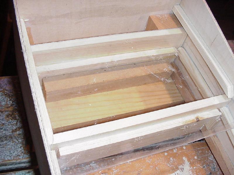
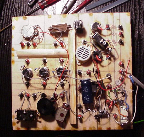
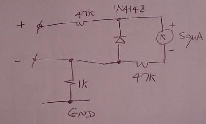
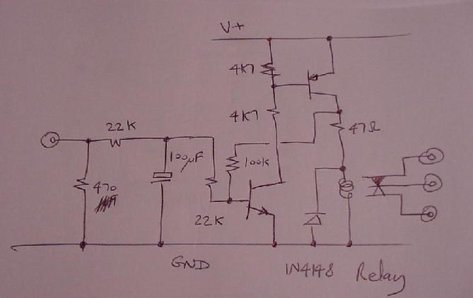
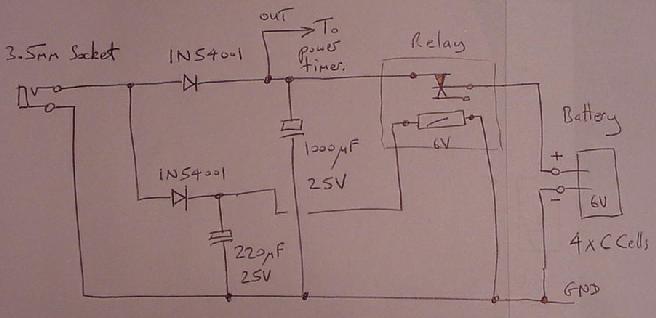
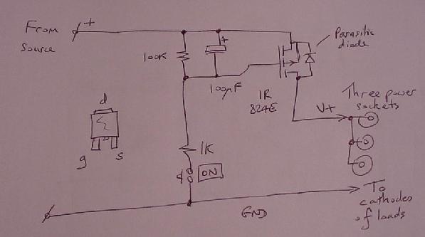
Also located under the perspex panel is a voltmeter. The scale was marked 0 to 50 microamps but the wiring sets this up as 0 to 10 volts. A pair of terminals are provided so that the meter can be used as a free-standing 10 volt meter. The negative terminal of the voltmeter is connected to the system ground via a 1K ohm resistor. This prevents a short circuit being created if the power supply is wired to this negative terminal. A diode prevents reverse voltages. The voltmeter can be used to monitor the power supply and battery condition by simply wiring its positive terminal to one of the supply point sockets. Components FittedAll of the load components were designed to have a resistance of about 500 ohms. Switches. A variety of switches are provided. Some are rotary, some toggle and others push buttone. Of the two push buttons, one is normally open and the other normally closed. Lights. 10 millimeter LEDs were provided. Some of these were wired with two socket connections so that they must be wired in series with other loads while the remainder have one socket connection. Current limiting resistors of 220R are fitted in series with each LED. Those provided with two sockets for series use are wired inside bridge rectifiers to make them polarity insensitive. Those with only one connection have their other retuned internally to the system ground. Buzzers. A pair of terminals provide access to a pair of noisy buzzer loads. These buzzers, purchased from Maplin, are actually piezo sounders with integral oscillators. Diode. Two sockets connect to a power diode. Capacitor. A large value capacitor is provided so that charging and discharging experiments can be conducted. It is accessed via a single terminal with its negative side internally returned to the system ground. Relay. A low-voltage relay is provided. A small hole in the front panel allows the movement of the contacts to be seen. Three patch sockets give access to a change-over set of contacts. Another socket provides access to the coil. A small circuit was implemented to raise the effective resistance of the coil to 500 ohms and to introduce a half second switching delay. The delay enables flasher circuits to be made and also stops the relay being destroyed by being wired as a buzzer. Variable resistor. A potentiometer is provided. It has a track resistance of one thousand ohms. Joiners. Two sets of three terminals are provided as joiners. These are simply connected together as two groups of three. Power Supply. Six volt power is used. Power can come via the rear 3.5 millimeter socket from an external battery eliminator or from the 4 cells in the rear battery compartment. The power unit contains a relay that disconnects the batteries when the external DC power is supplied. The power source unit feeds the rest of the device via the timer circuit. The unit is switched on with an electronic timer circuit. This is built from a high-power MOSFET. Owing to its high gate impedance and low on resistance, this is an ideal component for such a timer, resulting in very simple circuit. Three terminals are wired together as the output of the supply. Another three mirror these on the top panel. The relay amplifier circuit also requires a feed from the output of the power timer. Bottom Panel View showing the final assembly from underneath without the bottom panel. For future maintenance, if ever necessary, the bottom panel can be removed, since it is deeply recessed and glued on but lightly, with a few touches of wood glue. Out of Box Experience Thanks for looking at this web site. For information about online melody comparison using SongString technology, visit Melodybase. Design and Text copyright 2002, David Greaves. |